Step 01 What you should be checked in advance
System configuration
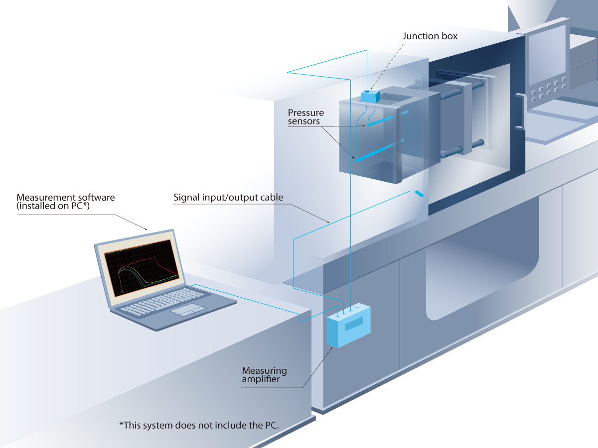
The basic configuration of the pressure measurement system MPS08B is as shown on the right.
Connect the pressure sensor to a connectable junction box and, through the junction cable, to the amplifier. Connect the amplifier to a PC with the measurement software installed via LAN cable. By connecting the molding machine and peripheral control devices via supplied signal input/output cables, it is possible to automatize measurement start, alarm signal output, and alarm signal cancellation.
PC Preparation
- Recommended PC operation environment
The recommended operation environment for the PC to be used by MPS08B is as shown in the table below.
* Connect the amplifier and PC with the supplied LAN cable. For this purpose, confirm that the prepared PC has a LAN port.
OS(Compatible with Japanese) Windows8(32bit・64bit)
Windows8.1(32bit・64bit)
Windows10(32bit・64bit)Processor Intel-made CPU Core i5 or higher Memory requirements 4GB or more Other Included with the Ethernet port, NET Framework 4.8 or later must be installed.
- Check whether the software can be installed.
Depending on your security environment, the measurement software may not be installed. Confirm in advance that the prepared PC is set in such a way that the software can be installed.
- Check whether the IP address can be set
After installing the measurement software, set the IP address of MPS08B as a network setting. Depending on your security environment, the existing IP address may be fixed and may not be changed. Confirm in advance that in the prepared PC, the IP address can be set.
■IP address set on MPS08B as default
IP address : 192.168.2.3
Subnet mask : 255.255.255.0(fixed)
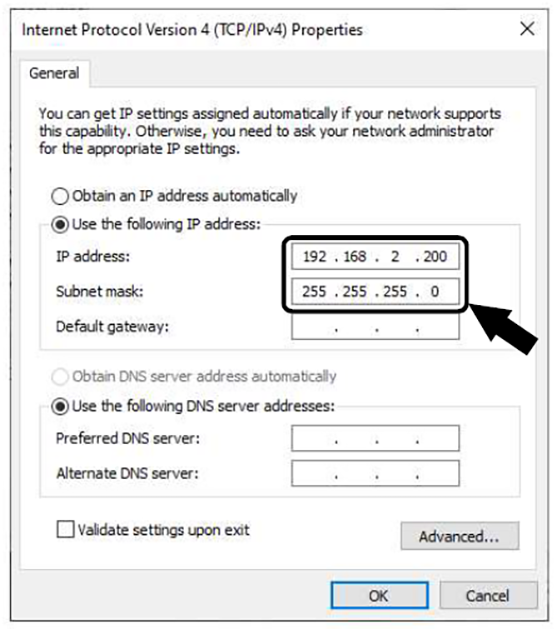
■IP address to be input to the PC
IP address : 192.168.2.200
Subnet mask : 255.255.255.0(fixed)
Default gateway : None
* If the IP address of the PC cannot be changed, change the IP addresses of MPS08B and the software by referring to the video on the “Step 03” page.
Molding machine check
- Preparation of trigger signal
The trigger signal is necessary for starting measurement. Confirm that the external device to be used, such as the molding machine, can output the signal.
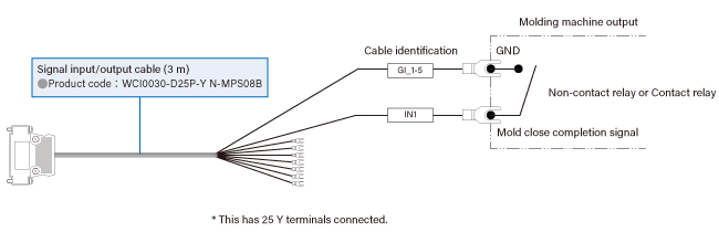
As “zero point reset” is performed simultaneously with the input of the trigger signal, we recommend that you input the signal while no pressure is applied to the sensor. Unless there is a special reason, connect the “mold close complete signal.” If the mold close complete signal is 24 VDC, make a contact signal by using a relay and connect as a trigger signal.●Circuit specifications
For input (trigger, alarm clear) to the MPS08B, use a no-voltage signal that is output on/off by a contact relay. With a variable voltage signal, MPS08B may not operate normally.
Example 1: when the output signal from the connected molding machine is “contact output”
Example 2: when the output signal from the connected molding machine is “voltage output”
Make connection via a relay that suits the voltage of the output signal from the molding machine.
When using a contact relay, use a type with built-in coil surge absorption circuit.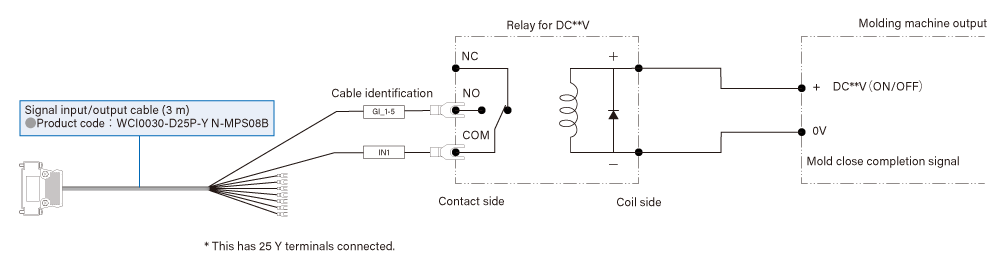
Power connection and installation space check
- Point of power supply connection
- ・The operation power voltage of the supplied AC adapter is 100 to 240 VAC. Check the power supply in advance for connection with the adapter.
- ・If the product is connected to the same power source as the molding machine, noise may be generated in the measurement values. Avoid connection to the same power source as the molding machine, and we recommend that you connect the product to a factory power source.
- Device installation space check
Check the installation locations of the amplifier and junction box in your factory, and confirm whether the lengths of the cables to connect devices are appropriate.
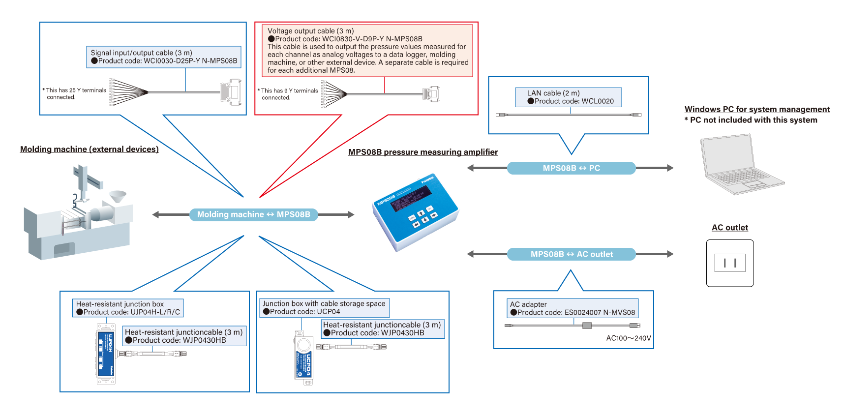
●Pressure measurement amplifier set MPS08B□-S system configuration diagram
In the pressure measurement amplifier set MPS08B□-S, the product set details is indicated by the blue frame. Optional products are by the red frame.
* The lengths of the sensor cables differ depending on the series and rating capacity. For details, download the catalog from the Material Download page and check it.