In-mold resin pressure measuring system
MPS08B pressure measuring amplifier
- Q1. What are the specific advantages offered by higher noise resistance?
A1. Higher noise resistance prevents malfunctions and adverse effects on the pressure measuring amplifiers and pressure sensors due to electromagnetic noise from electrical equipment and other devices nearby. This makes it possible to obtain consistent measurements, which in turn helps improve traceability management.
- Q2. How should multiple amplifiers be connected to allow simultaneous measurement of 24 channels?
A2. Use the amplifier interconnection cables (available separately) to connect multiple amplifiers. The corresponding number of junction boxes and junction cables are also required. (Cable product code: WCM0010-R6P-R6P N-MPS08B catalog page 31)
- Q3. Is it possible to edit waveform data imported to a PC?
A3. Waveform data is saved as CSV files on the connected PC and can be displayed in graph form.
- Q4. What is the purpose of the LAN port? Is wireless LAN connection possible?
A4. The amplifier is connected to the PC directly using a LAN cable. The LAN connection is used for high-speed communications. Wireless connection is not available.
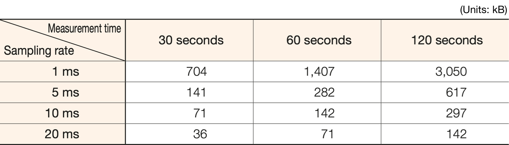
- Q5. What are the typical volumes of the data obtained?
A5. The volume of the waveform data will vary depending on sampling rate and measurement time. Refer to the table below.
- Q6. What happens when the PC runs out of available disk space?
A6. The pressure waveform will appear on the measurement screen. Once the hard disk capacity falls below the set available capacity, the “Available disk space” indication on the measurement screen will turn red. No data can be saved thereafter. We recommend transferring data elsewhere at frequent intervals.
- Q7. Can I use a commercially available LAN cable?
A7. Yes. (Depending on length, the cable may be susceptible to noise effects.)
- Q8. Can I view waveforms on the molding machine monitor?
A8.Yes. The MPS08B also provides an analog voltage output. If the molding machine has an interface for inputting an analog voltage and the machine is capable of displaying these values on the monitor, it can also display waveforms.
- Q9. Why is a trigger signal input to the amplifier required?
A9. The data is managed and monitored for each molding cycle shot. A trigger signal is input at the start of each shot. Zero resetting is also performed simultaneously to cancel temperature drift.
Ejector pin type pressure sensors
- Q10. Do the specifications for the previous sensors (EPS series) and new sensors (SS series) differ?
A10. The sensor flange diameter has changed from 5.7 mm to 6.0 mm.
The cable and connecting wires have also been modified to improve noise resistance. Thus, the connector type also differs.
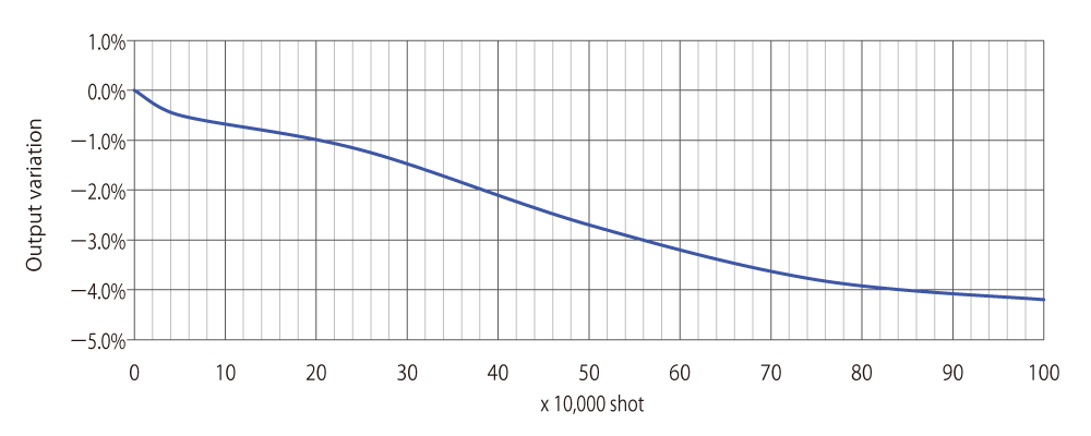
- Q11. How durable are the sensors?
A11. The sensors can withstand at least 1 million cycles in repeated load testing (at normal temperature, 80 MPa, with cycle period of 1.2 s, and 3 mm diameter). This does not constitute a guarantee. Factors such as usage conditions may affect durability.
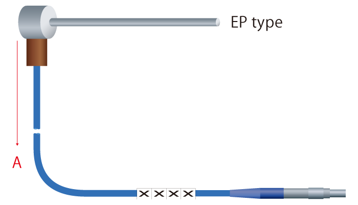
- Q12. How strong is the sensor cable attachment base?
A12. The maximum tensile force that can be applied to the cable perpendicular to the pin (direction A in the figure below) before it fails is 9.5 kg.
- Q13. Can the profile of the pin tip be machined?
A13. The profile cannot be machined for EP type pressure sensors, as machining to prevent rotation is not possible. However, using button type pressure sensors allows machining because existing pins can be used unchanged.
- Q14. Is it possible to measure mold release resistance (ejection force)?
A14. Yes. This can be determined from the waveform at ejection on the measurement screen.
ReferenceThe ejection force (N) can be obtained by multiplying the peak pressure (MPa) on the ejection waveform by the pressure sensor pressure-receiving area (mm2). Multiply by 0.102 to convert to units of kgf.
Calculation
exampleEjection peak pressure:C = 20(Mpa)
Pressure sensor diameter:d = φ3(mm)
Pressure sensor pressure-receiving area:S = (3×3×π)/4=7.0686(mm2)
Ejection force:P(N) = C×S=20×7.0686=141.4
141.4(N)×0.102=14.4(kgf)
- Q15. How do we check for sensor disconnection?
A15. A simple way is using a tester connector cable (available separately) to check whether a sensor is functioning.
(Tester connector cable product code: ATCS catalog page 31)
- Q16.Can the sensors be used with die-cast molding?
A16. Yes, provided the in-mold pressure does not exceed 100 MPa and the mold temperature does not exceed 150°C within the specifications range.
- Q17. Do the sensors include a temperature compensation circuit?
A17. No special temperature compensation circuit is included. Resistance fluctuations due to cable temperature and cable length are canceled by the circuit configuration. Strain gauge temperature drift is canceled by zero resetting when a trigger signal is input (at the start of measurement).
- Q18. Can the sensors be connected for measurement to commercially available measuring amplifiers?
A18.The sensors are based on proprietary Futaba specifications and cannot be connected for measurement to other instruments.
Button type pressure sensors
- Q19. When choosing button type pressure sensors, how should I determine the expected in-mold pressure?
A19. This is generally less than half the injection peak pressure. Refer to the data for the molding machine.
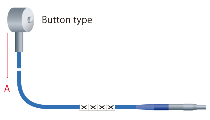
- Q20. How strong is the sensor cable attachment base?
A20. The maximum tensile force that can be applied to the cable in a vertical direction (direction A in the figure below) before it fails is 9.5 kg.
- Q21. Can I measure pressure if the lower flange face of the ejector pin is in contact with the protruding part of the sensor?
A21. Install so that the sensor and ejector pin centers are aligned (within ±0.3 mm).
- Q22. Machining the tip of the ejector pin to form a diagonal face alters the pressure-receiving area. How should the pressure be calculated?
A22. The pressure-receiving area is calculated as the projected area in the mold opening direction. The area for a 1 mm diameter round pin is calculated using the diameter 1 mm, even if the tip face is machined diagonally. The pressure acts on the diagonally cut face along a perpendicular axis, but this will be the same when converted to the pressure in the mold opening direction. This means you can use the same equation.
ExampleFor 1 mm diameter: Pressure-receiving area (mm2) × expected in-mold pressure (MPa) = 0.79 (mm2) × 120 MPa = 94.8 (N)
- Q23. What is the displacement of the sensor?
A23. The maximum displacement under the rated load is 0.02 mm.
- Q24.How durable are the sensors?
A24. Sensors can withstand at least 10 million cycles in repeated load testing (SSB01KN08×06: 23°C, 1,200 N, with cycle period of 0.5 s).
This does not constitute a guarantee. Factors such as usage conditions may affect durability.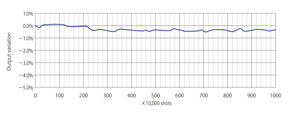
Compatibility of old and new products
- Q25. Can I use the earlier sensors (EPA, EPC, EPV) with the new sensors (SS series)?
A25. No. They cannot be used together.
- Q26. Can a new amplifier (MPS08B) be used with the earlier sensors (EPS series)?
A26. Yes, by connecting with an adapter (available separately). Note that CE compliance is assured only when used with the new sensors (SS series). (Adapter product code: ACAE01 catalog page 31)
Measurements with a mixed configuration of EPS series and SS series are not possible.
- Q27. How long will the earlier amplifiers (EPA, EPC, EPV, MPS08) and sensors (EPS series) continue to be sold?
A27. The earlier amplifiers will continue to be sold until stocks run out. The earlier sensors will continue to be sold for the foreseeable future.
- Q28. Does pin diameter affect measurements?
A28. With the EP type sensors, measurements are calibrated for each pin diameter, so measurements do not vary. With button type sensors, adjustments are performed by entering the pin diameter on the setup screen of the measurement software. Measurements do not vary.
Frequently asked questions
- Q29. The sensor cable broke.
A29. It may be possible to repair a damaged sensor cable for a fee,depending on the location of the breakage.Examination of the actual part involved is required. (Please contact your nearest Futaba sales office.)
※Repairs are generally possible if the breakage is at least 50 mm from the sensor flange.
- Q30. I did something that crushed the sensor connector.
A30. This can be repaired for a fee. (Please contact your nearest Futaba sales office.)
- Q31. No waveforms appear on the measurement screen.
A31. It may be due to a disconnection in the sensor or communication error between the amplifier and the PC. For information on checking the sensor, refer to Q17. A communication error may be due to poor connection. Try disconnecting and then reconnecting the cable.
- Q32. I’m not sure where to insert the sensor.
A32. You can measure pressure no matter where it’s inserted. To detect short shots, insert close to where short shots occur.
- Q33. I want to detect short shots, but I’m not sure what alarm monitoring zone threshold to use.
A33. The data obtained must be matched to product quality.One approach is to set a threshold based on tolerances provided for maximum and minimum peak data values saved for stabilized molding.
- Q34. What’s the ideal pressure waveform?
A34. Waveforms will differ, even for the same mold interior, depending on the sensor location. An ideal waveform can be described as one that can be consistently reproduced and meets required quality levels.
- Q35. I mistakenly input a voltage to the amplifier trigger signal.
A35. This can damage electronic components inside the amplifier. Connect to a nonvoltage contact input (e.g., a relay). The same applies for the alarm reset signal.
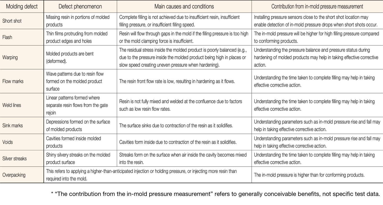
- Q36. What’s the correlation between pressure measurements and common molding defects?
A36. Refer to the following table:
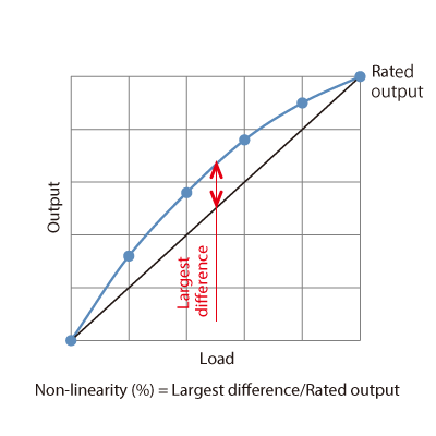
- Q37. What is nonlinearity?
A37. This is the value indicating the maximum difference between the calibration curve and the straight line connecting the output at zero load with the output at the rated load as a percentage of the rating.
- Q38. What are sensitivity fluctuations?
A38. Sensitivity fluctuations are fluctuations due to fluctuations in operating temperature. They are expressed as fluctuation rate per 1°C.
Miscellaneous
- Q39. Are instruction manuals available in other languages?
A39. An English language instruction manual is available. Instruction manuals in other languages are planned for the future.
- Q40. What is the language-switching function on the measurement software?
A40.This function on the measurement software screen allows the user to switch languages at the touch of a button. It currently supports English and Japanese. Other languages will be added in the future.
- Q41. What does the CE marking mean?
A41. The CE marking is a standards compliance marking required for specified products sold in the European Union (EU). It indicates compliance with the Essential Safety Requirements (ESRs) stipulated by the EU (EC) directive. “CE” is an acronym for the French phrase “Conformité Européene” (European Conformity). Products undergo specified compliance evaluations by the manufacturers (importers) or third-party certification bodies and carry the CE marking on the products themselves, on packaging, and on accompanying documentation, guaranteeing free retail and distribution within the EU region. There are two procedures, depending on the specific product: cases in which certification is obtained from a third-party certification body (“Notified Body” or “NB”) and cases in which self-certification is acceptable. The CE marking is required only when exporting to EU countries (from Japan External Trade Organization (JETRO)). Compliance with European standards, however, can be said to demonstrate high performance and safety.