Precautions on use of sensor
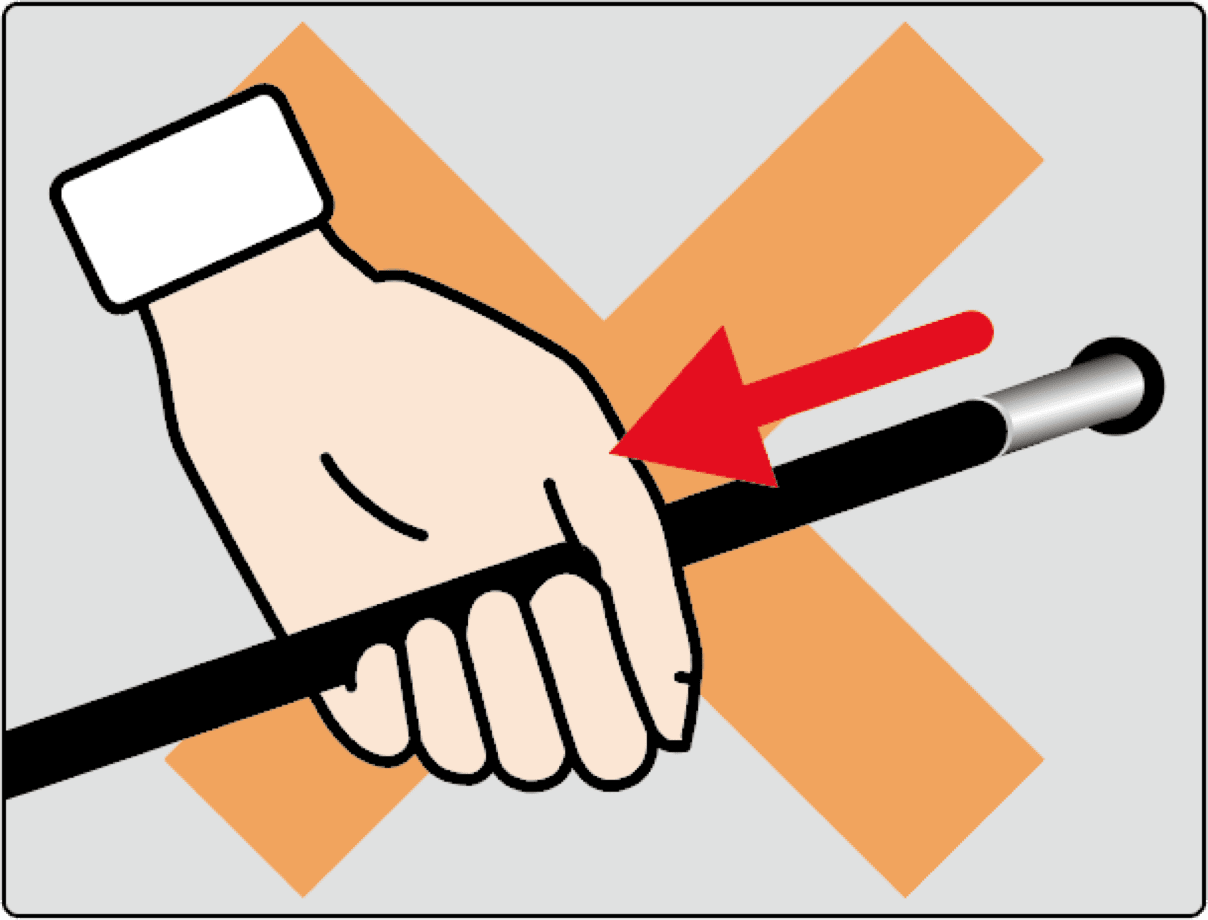
DO NOT pull the cable!
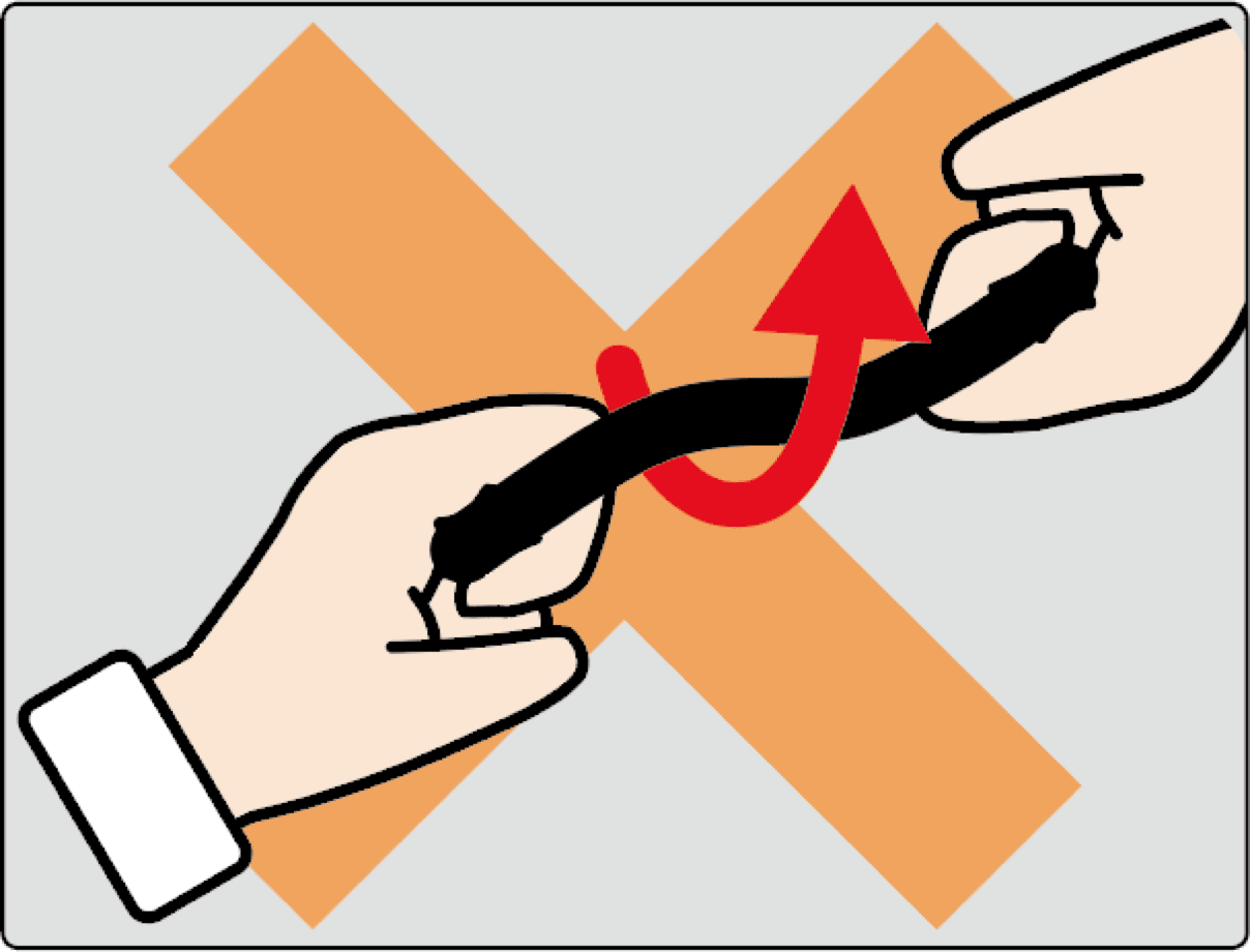
DO NOT twist the cable!
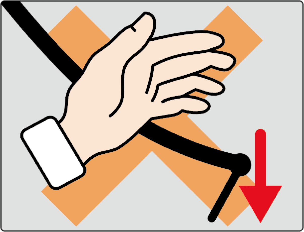
DO NOT drop the cable!
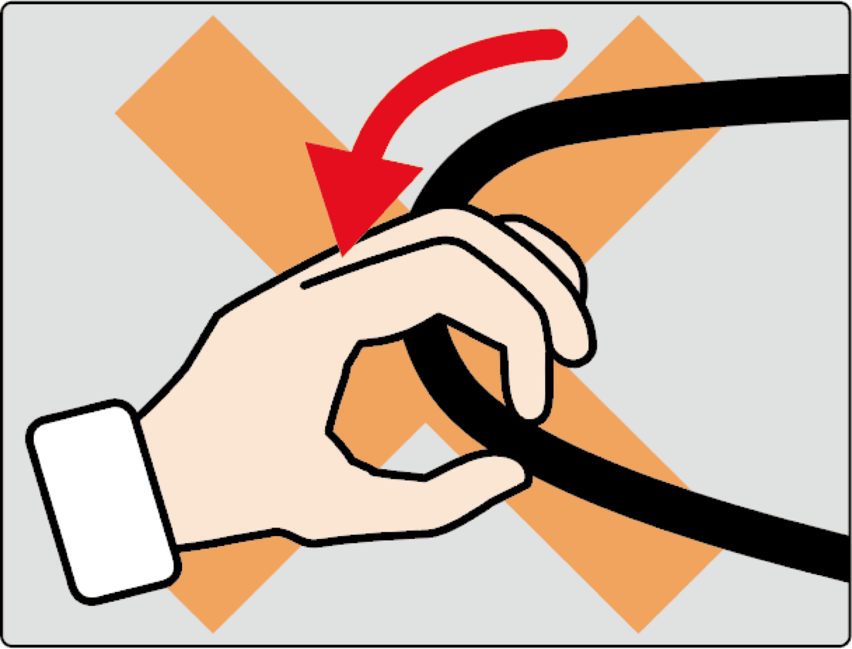
DO NOT bend the cable to an excessively small radius!
- 1. Note that pulling or twisting the cable may cause it to be broken.
- 2. In order that no excessive force is applied to the connector of the connection cable, do not connect the cable in a strained condition. Pulling the cable or applying an excessive force to it may cause a failure, interruption of measurement, or measurement value abnormality.
- 3. Make absolutely sure that electric current never flows in the sensor body.
- 4. Do not disassemble the interior of the sensor. Failure to follow this instruction may impair its functionality and safety.
- 5. When disposing of this product, give consideration to the environment.
- Target products
- Pressure sensor: ejector pin type SSE series
- Pressure sensor: button type SSB series
- Pressure sensor: SCB series for junction boxes with cable storage space
- Direct pressure sensor: SPF
- Resin temperature sensor: ejector pin type EPSSZL series
- Resin temperature sensor: flush-mount type EPSSZT series
- Mold surface temperature sensor: STF
- Flow rate sensor: SMF
- Flow front detection sensor: ejector pin type DISSZL series
- Flow front detection sensor: flush-mount type DISSZT series
Pressure sensors
Notes on installation and measurement
- 1. An ejector pin type pressure sensor can be used for ejection as with ordinary ejector pins.
- 2. Do not connect the pressure sensor to amplifiers other than our pressure measurement amplifiers MPS08B and MPV04.
- 3. To conduct accurate measurement, it is necessary to set the output sensitivity. For how to set the output sensitivity, refer to the instruction manual for the pressure measurement amplifier (* The [sensitivity grede] may differ from piece to piece even when the pin diameter is the same).
- 4. The heat resistant temperature is 150 ℃ or below at the sensor unit. If heat hotter than the resistant temperature is to be applied, it is necessary to cool the sensor unit. Use the sensor within its operation temperature range.
- 5. The measurable pressure range of the ejector pin type is up to 100 MPa. If a force greater than this is applied, the sensor unit may be broken or the pin may be deformed.
- 6. Do not allow the measurement range of the button type sensor to exceed the rating capacity. If a force greater than it is applied, it may be broken or deformed.
- 7. The cable bending radius is 24 mm or more for the SSE series and SSB series, 10 mm or more for the SCB series, and 20 mm or more for the direct type pressure sensor SPF. If a given cable is bent to a radius below the corresponding cable bending radius, it may be broken.
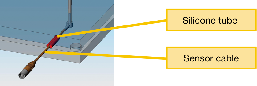
- 8. As a sensor installation method, we recommend that you secure the cable by setting a packing (supplied silicone tube) between the spacer type ejector plates (figure below).
[Ejector pin type: diagram of an example of recommended incorporation method]
Notes on processing of ejector pin type pressure sensor
- 9. The pin can be cut to the same length as a regular ejector pin. The pin must be cut perpendicular to the pin axis; the pin rotates with respect to the flange section.
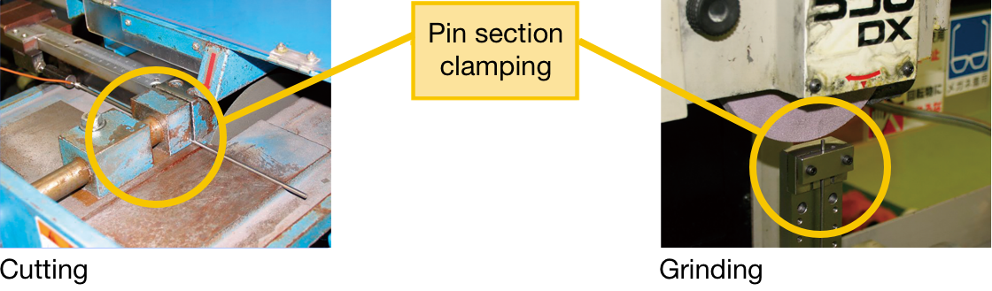
- 10. The sensor unit (flange section) is not waterproof. As oil for submerging resin and others, dust, or the like may get into the sensor and cause a short-circuit or breakage, we recommend that you conduct dry cutting and dry polishing (grinding).
- 11. When processing the sensor, be sure to hold the pin unit. If the sensor unit (flange section) is clamped and deformed, its interior may be broken and it may become impossible to conduct appropriate measurement. Also, pay attention not to allow excessive vibration to be applied to the sensor unit. As a sensor is incorporated in the flange section, it is not possible to cut the flange.
- 12. Never conduct cutting or length adjustment of the sensor using a sander, a grinder, or the like because doing so may lead to breakage of the sensor unit.

- 13. Never conduct processing of the pin side face except for cutting of the tip because doing so leads to breakage of the sensor unit or shortening of its service life.
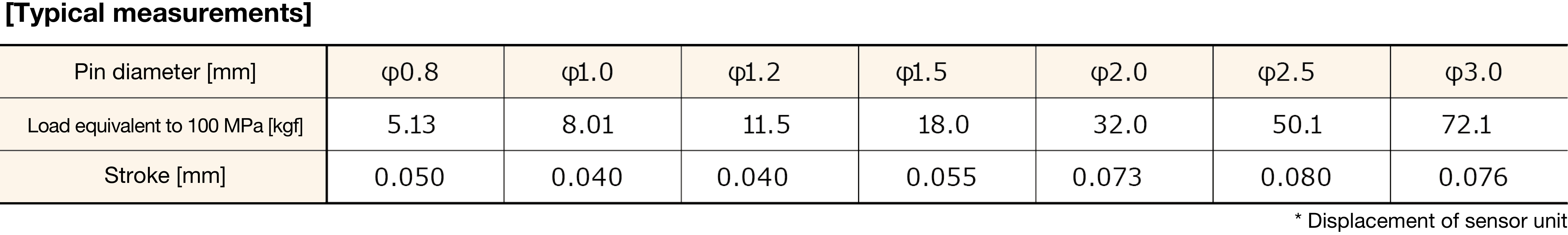
- 14. When a pressure is applied to an ejector pin type resin pressure sensor, its pin moves in the vertical direction (shortening direction) due to the structure of the sensor. Guides for the stroke amount when a load equivalent to a pressure of 100 MPa are as shown in the table below. If a molded item has the unevenness in its shape, set the length by referring to the corresponding stroke amount in the table below as a guide.
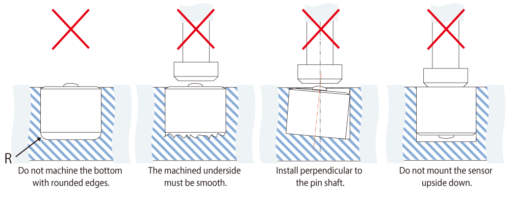
Notes on incorporation of button type pressure sensor
- 15. Install button type pressure sensors by paying attention to the following points.
Resin temperature sensors
Installation and measurement
- 1. An ejector pin type pressure sensor can be used for ejection as with ordinary ejector pins.
- 2. Pay attention not to drop the sensor because quartz fiber is used in its interior.
- 3. The heat resistant temperature is 150 ℃ or below at the sensor unit.
- 4. The withstand pressure is 150 MPa or below. If a load greater than that is applied, the sensor may be broken.
- 5. The cable bending radius is 50 mm or more. If a given cable is bent to a radius below this, the cable may be broken.
- 6. To conduct accurate measurement, it is necessary to set the output sensitivity. For how to set the output sensitivity, refer to the instruction manual for the resin temperature measurement amplifier EPT001S (* The [sensitivity grede] may differ from piece to piece even when the pin diameter is the same).
- 7. If the tip of the connector becomes dirty, sensor sensitivity will be affected. If it becomes dirty, wipe off dirt with a clean, soft cloth.
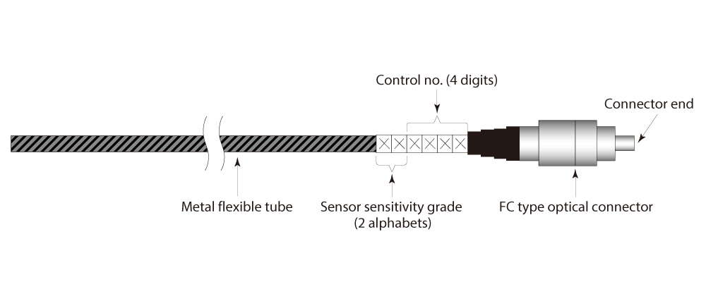
[Ejector pin type resin temperature sensor – Part where sensitivity grede is indicated]
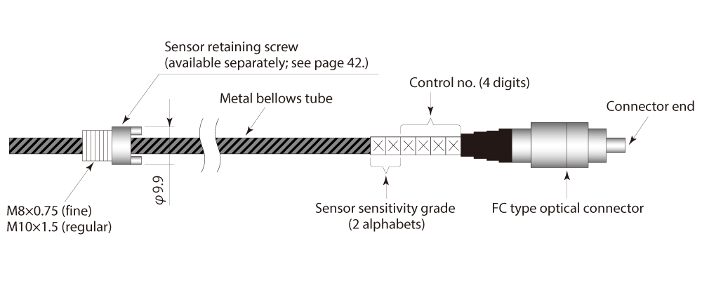
[Flush-mount type resin temperature sensor – Part where sensitivity grede is indicated]
Note on processing
8. Never conduct additional processing of the pin unit because doing so may cause the internal fiber to be broken.
Mold surface temperature sensors
Installation and measurement
- 1. The heat resistant temperature is 220 ℃ or below at the sensor unit.
- 2. The withstand pressure is 150 MPa or below. If a load greater than that is applied, the sensor may be broken.
- 3. The cable bending radius is 6 mm or more for STF01.0X11.5X18.5 and 10 mm or more for STF04.0X08.0X026. If a given cable is bent to a radius below the corresponding cable bending radius, it may be broken.
Note on processing
- 4. Never conduct additional processing of the pin unit because doing so may cause the thermocouple measurement unit to be broken.
Flow rate sensor
Installation and measurement
- 1. Pay attention not to drop the sensor because an optical fiber is used in its interior.
- 2. The heat resistant temperature is 150 ℃ or below at the sensor unit.
- 3. The withstand pressure is 150 MPa or below. If a load greater than that is applied, the sensor may be broken.
- 4. The cable bending radius is 50 mm or more. If a cable is bent to a radius below the cable bending radius, it may be broken.
- 5. If the tip of the connector becomes dirty, sensor sensitivity will be affected. If it becomes dirty, wipe off dirt with a clean, soft cloth.
Note on processing
- 6. Never conduct additional processing of the pin unit because doing so may cause the internal fiber to be broken.
Flow front detection sensors
Installation and measurement
- 1. Pay attention not to drop the sensor because quartz fiber is used in its interior.
- 2. The heat resistant temperature is 150 ℃ or below at the sensor unit.
- 3. The withstand pressure is 150 MPa or below. If a load greater than that is applied, the sensor may be broken.
- 4. The cable bending radius is 50 mm or more. If a cable is bent to a radius below the cable bending radius, it may be broken.
- 5. If the tip of the connector becomes dirty, sensor sensitivity will be affected. If it becomes dirty, wipe off dirt with a clean, soft cloth.
Note on processing
- 6. Never conduct additional processing of the pin unit because doing so may cause the internal fiber to be broken.